Abstract
There is a growing need for humans to perform complex remote operations and to extend the intelligence and experience of experts to distant applications. A blending of human intelligence, modern information technology, remote control, and intelligent autonomous systems is required, and the authors have coined the term teleautonomous technology, or teleautomation for short, for methods for producing intelligent action at a distance. Teleautomation goes beyond autonomous control in that it blends in human intelligence and action as appropriate. It goes beyond teleoperation in that it incorporates as much autonomy as is possible or reasonable.
A new approach for solving one of the fundamental problems facing teleautonomous systems is discussed in detail: the need to overcome time delays due to telemetry and signal progagation. New concepts, called time and position clutches, are introduced; these allow the time and position frames, respectively, between the local user control and the remote device being controlled to be desynchronized. The design and implementation of these mechanisms are described in detail. It is demonstrated that these mechanisms lead to substantial telemanipulation performance improvements, including the novel result of improvements even in the absence of time delays. The novel controls also yield a simple protocol for hand-offs of control of manipulation tasks between local operators and remote systems.
* Parts of this paper were presented at the Second AIAA/NASA/USAF Symposium on Automation, Robotics and Advanced Computing for the National Space Program, Washington, D.C., Mar. 11, 1987, and at the IEEE International Conference on Robotics and Automation, Raleigh, NC, Mar. 30, 1987. This version was published in the IEEE Transactions on Robotics and Automation, Vol. 6, No. 2, April 1990. This research was performed at the Robotics Research Laboratory, College of Engineering, University of Michigan, Ann Arbor, Michigan, with support from the Research Excellence Fund of the State of Michigan and an equipment grant from Silicon Graphics, Inc.
L. Conway and M. W. Walker are with the Dept. of Electrical Engineering and Computer Science, University of Michigan, Ann Arbor, MI 48109. R. Volz is with the Dept. of Computer Science, Texas A & M, College Station, TX 77843.
CONTENTS
2. OVERVIEW OF TELEAUTONOMOUS OPERATION
3. BASIC TELEAUTOMATION CONTROLS
3.5 Task Handoffs and Rendevous
4. TELEAUTONOMOUS SYSTEM ARCHITECTURE
4.3 Remote Controller and Queue
There is a growing need for humans to be able to perform complex, large scale, remote operations, and to extend the intelligence and experience of experts to distant applications. For example, the National Commission on Space report Pioneering the Space Frontier [NAS86] describes many potential scientific, commercial and colonization activities that could be accomplished in space over the next 50 years, and the Ride report Leadership and America's Future in Space [RID87] discusses specific missions that could be adopted, all of which require remote extensions of intelligence and action. Undersea operations, mining, public safety, nuclear power maintenance, various defense applications and a wide variety of other hazardous operations are examples of terrestrial applications that would benefit from an increased capability to perform complex remote operations. In this paper, we present a novel technique that can help achieve this type of operation.
The terms robotics, teleoperation, telepresence, artificial intelligence and "expert systems appear throughout [NAS86] and [RID87] as the kinds of technologies needed to achieve the necessary remote operations. None of these technologies as developed to date, either alone or in combination, are sufficient to satisfy the need for remote intelligence and action, though they represent important steps towards that goal. The term telerobotics has been used to represent human control of remote mechanisms, including supervisory control of mechanisms having some degree of autonomous capability. NASA in particular has carried out and considerable work in developing telerobotic systems over recent years (e.g., see [AND89], [HAR89], [JAU89], [KAN89a], [KAN89b], [MAT89], [WIL89]), and the literature is replete with papers discussing humans in control systems, (e.g. see [BEK61], [PHA69a], [PHA69b]). However, the scope of problems being addressed through telerobotics does not represent the full range of systems and the full problem space that might fruitfully be studied.
Figure 1.1 shows our view of this basic problem space. An element of intelligent activity is an entity at a specific location performing a process (perception, cognition, or action), represented as a point in this space. Intelligent activity is a symphony of these elements connected by processes of communication, much the same way that language is formed of the elements of grammar and the rules governing their use. The space is discrete, and a single entity may be represented by more than one point (but all on a single location plane) if it performs more than one process.
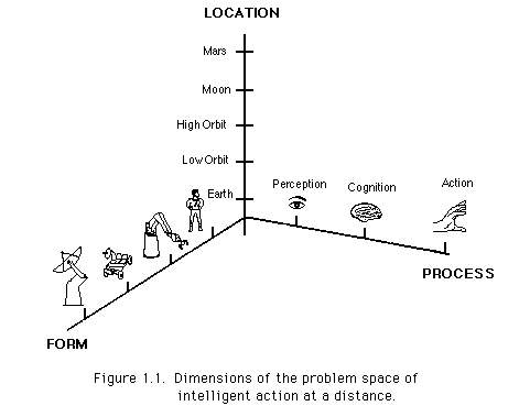
These dimensions imply a wide range of systems that are possible. Many kinds of devices, not just robots and vehicles, are possible. Manned operations are included. Perception, cognition and action may be divided or shared among entities. Cooperating entities may be at different locations. Cooperative relations among the entities may be dynamic. For example, telecontrol of a device may be handed off between different humans in different locations. And, groups of humans and machines at different locations may be able to cooperate dynamically. For example, in one future scenario, humans at scattered locations -- for example, on Earth and in the Space Station -- may cooperate on a repair satellite task using remote robots, as sketched in Figure 1.2.

Existing telemanipulation, autonomous and telerobotic approaches can also be viewed from this perspective. For example, a standard telemanipulation system would have two points in the human plane indicating perception and cognition, and a single point in the manipulator plane, indicating remote action. An autonomous system would be a set of three points in the plane of some device. The traditional approaches are thus seen as constrained to a set of three points lying in one or two planes perpendicular to the "form" axis. Telerobotics relaxes the constraints by allowing both the human and robot plane to have points of the same process type, indicating a sharing of the process, which most commonly is cognition. Our broader perspective simply makes it clear that there are many additional combinations that need to be considered.
We use the term teleautonomous technology [CON87a, CON87b], or teleautomation , to emphasize the interactions of humans with remote, intelligent, partly-autonomous systems of many forms (not just robots or vehicles). We specifically include in our view of teleautonomous activities systems involving several humans and several partly autonomous systems in coordinated activities. Thus teleautonomous system technology will also blend in the methods of collaboration technology or computer supported cooperative work for effective goal-seeking coordination in such multi-agent systems [GRE88].
For example, the intelligent agents at the remote location need not be autonomous devices but might well be intelligent, but non-expert, humans. Many operations, such as infrequent maintenance operations or actions ensuing from unforeseen events, will be difficult or impossible to automate. Teleautonomous technology will allow experts in one location to guide non-experts located elsewhere more effectively than is currently possible. The payoff in terms of reduced training costs (many astronauts trained for months to perform a 45 minute repair on Solar Max [ESS85]) and the extension of operations that can be performed in space could be significant.
Teleautonomous system theory is far from being fully developed. In this paper we present some fundamental principles we believe will be important in most teleautonomous systems encompassing large distances or having large telemetry delays. In Section 2 we present a high level overview of the operation of teleautonomous systems. In the remainder of the paper, we present some fundamental principles we have discovered thus far. Section 3 describes the basic ideas of time and position desynchronization that are necessary for defeating the time delays that occur when the operations are spread over substantial distances. The implementation details of the time and position clutches (and associated mechanisms) that realize the time and position desynchronization are described in Section 4. In Section 5 we present experimental results that verify the utility of using time and position desynchronization. Remarkably, these results show improved performance even when there is no time delay to defeat. Section 6 discusses future research directions in the teleautonomous area. Our conclusions are presented in Section 7.
2. OVERVIEW OF TELEAUTONOMOUS OPERATION
Figure 2.1 shows, at a conceptual level, the structure of a single local-remote pair in a basic teleautonomous system. The spatial reference frame is taken to be that of the human controller at the left, that is, the controlled environment is remote. The controlled environment can include humans or any manner of device or both. The remote intelligent controller receives data from multiple sensors, and provides multiple outputs encompassing anything from servo-level control signals to a robot joint, to video signals to a heads-up display worn by a remote human.
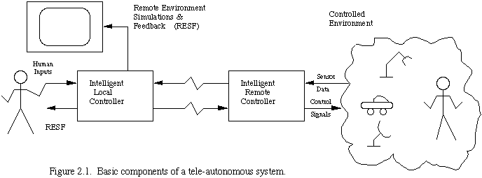
The inputs on the local side of the system may be any form of input control by the human, from simple joystick control, to complex cockpits with many inputs, to discrete commands for the remote controller to perform complex tasks. The local display represents any kind of feedback to the human about the remote environment. This will include both simulated information and actual feedback signals and may be composed of TV images, complex graphics, force reflection on input devices, or even high speed data analysis. The distance between the local and remote sites can produce substantial time delays in the signal transmission between them.
Teleautonomous control of even a single local-remote controller pair provides many operating modes, including:
1) Direct continuous teleoperator control of a remote device. The remote controller merely follows its inputs. This is currently the most common form of operation.
2) Shared continuous teleoperator control of a remote device. The remote controller performs higher level control than position servoing. For example, it might treat received inputs as being relative to an object to be manipulated and perform appropriate transformations before following them [VOL88]. Or, it might treat received inputs as a nominal path, and perform some local sensing and replanning to reach the goals of the nominal plan.
3) Discrete command control by the human operator of the remote device. This implies a higher level of capability in the remote portion of the controller that can vary from simple set-point control of a number of satellite antenna positioning servos, to complex task analysis, planning and execution. At this level the commands become highly task specific, though the lower level primitives utilized may be more generic.
4) Supervisory control1. The remote device operates in a largely autonomous mode and only interacts with the human when it encounters a situation it cannot handle, (management by exception), or in which the human notices an opportunity to improve performance (opportunistic management). It differs from the discrete command mode principally in the frequency of interaction with the human controller, and the philosophy of being largely autonomous. One local human operator might supervise a fleet of remote devices.
1[We use the term supervisory control to describe a much higher level mode than that usually attributed to the term. However, our usage fits the intuitive interpretation of the term quite well].
5) Learning control. The remote controller is given an intelligence that allows it to learn from human inputs and sensor information, and subsequently deduce correct behavior in similar situations without human intervention.
6) Guidance of remote non expert humans by local experts. In this mode a variety of media, such as visual displays, graphics, touching, and pointing, are used to achieve a collaboration between the local expert and the remote non-expert.
Groups of such basic systems, possibly with local controllers in different locations, will make up larger scale teleautonomous systems. Many kinds of interactions will be possible, from hand-offs of control between different local control agents (even if in different physical locations) to shared cooperative action of the remote devices.
We present here a sequence of interface control concepts that collectively underlie efficient control of manipulation tasks and also enable simple protocols for exchange of such tasks among control agents.
3. BASIC TELEAUTOMATION CONTROLS
Fully general teleautonomous systems with all of the capabilities described in the previous sections do not yet exist, and will be the subject of considerable future research. In this section we present a conceptual overview of basic human interface and system architectural concepts that we believe to be suitable for incorporation into almost any general utonomous system. We introduce the specific teleautonomous problems that these concepts address and methods for measuring the effectiveness of their implementations. Section 4 then describes in detail one basic implementation of the mechanisms.
One of the most fundamental problems facing teleautonomous systems is time delay due to telemetry and signal propagation delays. Even modest time delays have long been known to cause instabilities in control systems such as robots [MUR66]. In addition, the time delays present in space applications are anything but modest. They are currently handled by a very inefficient "move a little and wait" mode of operation.
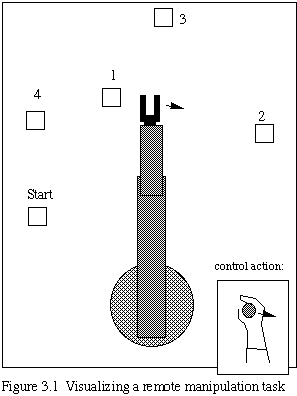
To provide a measure for the effectiveness of the control methods we develop, we introduce a simple experiment similar to accepted tests for human performance on direct manipulation tasks. Suppose that we are looking via video link over the shoulder of a telerobotic manipulator, and controlling the manipulator via a joystick as shown in Figure 3.1. We are to perform the simple task of touching in sequence each of a series of boxes. This is a standard test of human manipulation cabability, and the task's difficulty, that is, the time to complete the task, has been shown to be a function of the ratio of the distance between consecutive boxes and the sizes of the boxes [CAR83]. The difficulty can be varied easily, and we can undertake various trials of performance as a function of system parameters. For example, we could do some simple trials to see whether the time to complete the task is a logarithmic function of the ratio D/S, as in Fitts' Law [CAR83].
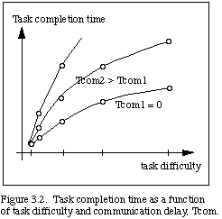
To demonstrate the consequences of time delay, we visualize the same manipulation experiment with a time delay inserted into the communications path. We find that the telerobot's motions then tend to be rather slow and jerky. The operator must move a little and then wait through the time delay to see what happened. The difficulties introduced by the time delay are quite noticeable, and task completion time may be greatly extended as a function of the delay, as shown in Fig. 3.2.
Such experiments (and others to be described subsequently) were performed with a real telerobot controlled from a force-driven rate joystick. Instead of using a live video display, however, we displayed a model of the telerobot (a PUMA) using a Silicon Graphics IRIS workstation. The model was driven by the actual joint angles of the telerobot, and was thus equivalent to observing video of the real telerobot. Various simulated time delays (discussed hereafter) were easily implemented using this approach.
Over the past several decades, there have been numerous attempts to overcome the difficulties of time delay in control systems. In one way or another, all approaches have been based upon some form of prediction with respect to the time delayed sensed signal. At a servo level, feedforward control that does not encounter the time delay has been used. Kelly [KEL67] found that predictive display of one or more system variables under operator control was useful, and that substantial improvements in submarine operation could be achieved through such means. Bernotat and Widlok describe the use of mechanical prediction [BER66]. Another use of predictor displays was for orbital rendezvous [MCC65]. A more recent study of similar nature [MIL85] has shown that performance degradation due to time delays in rendezvous and docking maneuvers can be reduced via use of prediction.
In an attempt at overcoming time delays in controlling remote manipulators, Ferrell and Sheridan [FER67] built a local manipulator having similar dynamics to the remote manipulator. The operator controlled the local manipulator, where no time delays were present, with the control signals being sent to the remote manipulator as well.
From the telemanipulator perspective, remote operations have been studied for years (e.g., see [GOE52], [KUG72], [HIL79], [DRA87], MOL87] ), with little emphasis on time delays, except for the predictive manipulator cited above. More recently, Noyes and Sheridan [NOY84] have extended the predictive manipulator idea by using a predictive display. The operator controls a local simulation of the telerobot, with the control signals then sent in parallel to the simulation and the remote telerobot. The simulation is then displayed superimposed over the return video. In this way the operator can "see" the effects of the control immediately without having to fully wait for the return signal from the telerobot.
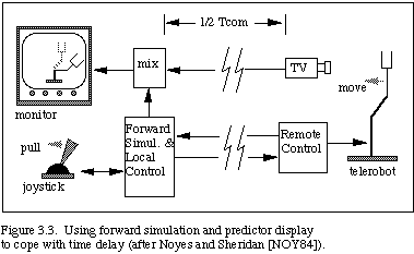
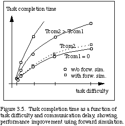
This predictive display system concept is sketched in Fig. 3.3. Figure 3.4 presents a visualization of telerobotic manipulation using the forward simulation to cope with the time delay. The wire frame is the forward simulation that directly responds to operator control, and the solid frame represents the time delayed image of the real telerobot. Much faster and smoother control is achieved using forward simulation. The task time may be reduced to nearly that of the no-delay case, as shown in Fig. 3.5. This is a first step towards evolving machine manipulation visualization, since the visualization could help cope not only with communication delays, but also with computational delays within a self-contained autonomous agent.

We note that the simulation used in our experiments is kinematic. A more accurate system would result if dynamic simulation were used instead. However, for certain applications, as well as for testing the concepts we are introducing, a kinematic simulation is sufficient. For example, unless the inputs to our robot control on the PUMA (which has been modified to be substantially superior to that supplied by the vendor) contain significant high frequency components, the actual robot output tracks the input very closely, and as long as we are moving in free space at moderate speeds or performing only coarse operations involving contact, the kinematic simulation is sufficient. We expect that for high tolerance operations involving both time delay and contact among encountered objects some additional mechanisms, such as partially autonomous operation, will be necessary. Nevertheless, the kinematic simulation is perfectly adequate to demonstrate and characterize the ideas presented here.
In the work of Noyes and Sheridan described above, the time frames of the simulation and the robot are separated by the time delay of the telemetry and propagation. However, there is no intrinsic reason to maintain this synchrony. The simulation could be allowed to operate faster than real-time, stretching out the separation between the simulated and actual robots. Moreover, forward simulation can also be exploited even if we don't have a communications time delay.
In order to seize these opportunities, we introduce the concept of a "time clutch" that can disengage synchrony between operator specification time and telerobot manipulation time during path specification. Our hypothesis is that operators can often think of and generate a path segment more quickly than the telerobot can follow it. This is particularly true of large space telerobots such as the Remote Manipulator System (RMS) [NAS81]. Once generated, such a path segment can then be followed more quickly by the robot than would be the case if the robot were time-synchronized to the specification process; with time synchrony disengaged, the robot can steadily proceed at nearly its maximum rate, subject of course to error limits and hard constraints.
Figure 3.6 shows a path being generated well out in advance of the actual robot by an operator using forward simulation with time clutch disengaged. The performance of an operator when using the time clutch while performing the task of touching a series of boxes in our experimental trials is shown in Fig. 5.2 (and described in detail in Sect. 5.2). Remarkably, the performance is better than control without the time clutch, even in the case of no time delay.

This step in the evolution of machine manipulation visualization enables the cognitive agent to "look and think ahead" of the manipulation under control, with the look-ahead time being elastic, and not just a fixed internal or external system time delay. The implementation of this new capability requires only a simple mutation of the forward simulation previously used for coping with a time delay.
Figure 3.7 presents an overall diagram of the basic system architecture, modified to include the time clutch. Also shown are the position clutch and other controls to be described in subsequent sections.
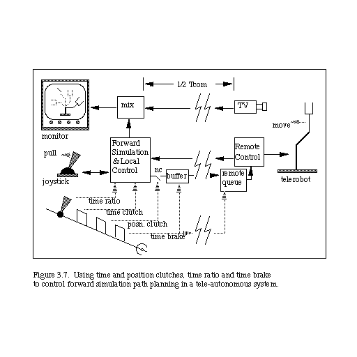
We next introduce the concept of a "position clutch" which enables a disengagement of position synchrony between simulator and manipulator path (see figure 3.7 for system diagram). We hypothesize that faster, shorter, cleaner paths can be generated on difficult tasks using this control. This idea is illustrated in Figure 3.8, which shows the use of the position clutch to disengage from path generation during a close approach to a difficult manipulation (in this case, touching a small object).

Suppose, for example, that the operator had arrived (in the simulation) at point A ahead of time by using the time clutch. The position clutch can then be disengaged, stopping the output from the operator control from going to the real telerobot - - it will only go to the simulation. When the forward simulator is in a good position, the position clutch will be reengaged, causing a short, smooth path to be inserted that links to the earlier path. This avoids inclusion of jittery prepositioning movements in the final path that will be followed. Furthermore, the time spent by the operator in achieving the proper position will not be incurred by the real telerobot since these motions were "clipped" out of the path sent to the telerobot.
The operator has thus used up some of the time saved through use of the time clutch, with the result that the overall task time of the telerobot is reduced still further. This level of manipulation visualization corresponds to quick visualizations and visualized trials of multiple alternatives prior to commitment to action, and its implementation requires only another simple mutation of the basic forward simulation capability.
To handle contingencies and errors we introduce the concept of a time brake. This control can be used to deal with situations such as something falling over a previously generated path, as illustrated by the "X" in Figure 3.9. In Figure 3.9 we see the time brake being applied and the forward-simulated manipulator backing down the path (in a race to get on the other side of the obstacle before the real system gets there).
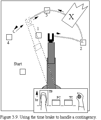
This aspect of visualization corresponds to seeing something about to happen that will interrupt an action previously visualized but not yet underway. If it had gotten underway, or is allowed to get underway, the system will have to deal with it through local reflex action or crash. But, if visualized in time, the cognitive agent can withdraw the action using the time brake.
3.5 Task handoffs and rendezvous
These basic teleautonomous system interface controls enable us to greatly improve telemanipulation performances, as we will see in the discussion of our initial experimental results, but the controls do more than that. They also provide the basis for a simple, elegant protocol for hand-offs and rendezvous of tasks between different control agents.
Imagine two operators, one in control of the telerobot and the other about to take over in relief of the first, as sketched in Fig. 3.10. Each operator controls a simulation of the telerobot, but only the control signals of the first are sent to the real telerobot. The relief operator would, with position clutch disengaged, guide his/her simulation as close to the first operator's as possible (or as close as required, as a function of the interpolation and smoothing methods to be used in the rendezvous). The first operator then disengages their position clutch, leaving the path "hanging". Figure 3.11 shows this moment in the interaction.
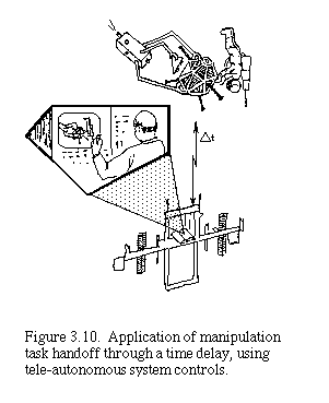

The second operator then engages their position clutch, rendezvousing with the path and taking control of future path generation. When the actual manipulator passes over this path segment, it will do so smoothly and will not notice that a change of control agent has occurred in mid-maneuver. We can again find interesting biological analogies to this visualization situation. For example, consider the interactions among basketball players as they previsualize fast-paced multiplayer interactions.
We believe that this simple protocol can be built upon to mechanize quite a wide range of manipulation interactions between autonomous agents.
4. TELEAUTONOMOUS SYSTEM ARCHITECTURE
In this section we describe the details of the basic teleautonomous system architecture used in our experimental trials (see results in Section 5). A schematic of the basic system architecture is given in Figure 4.1 (adapted from [CON88]), which expands upon the basic system diagram given earlier in Figure 3.7.
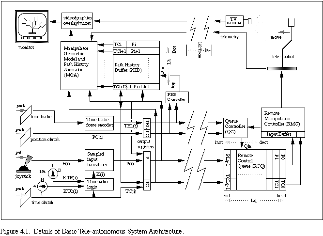
The "controller/simulator" part of Fig.3.7 has been detailed in Fig. 4.1 into subparts. These parts are the sampled input transducer, the path history buffer (PHB), the PHB controller, the manipulator geometric model and path history animator (MGA), the time brake force encoder and the time ratio logic.
The "remote controller" of Fig. 3.7 is detailed in Fig. 4.1 as consisting of the remote manipulation controller (RMC) that can faithfully follow new position commands, and its input register for holding command values received from the "queue". The "queue" of Fig. 3.7 is detailed in Fig. 4.1 into two major subparts, the remote control FIFO queue (RCQ) and its associated queue controller (QC).
We now describe the functions and interactions of the various components of this architectural structure. Additional details of architectural structure and function are given in [CON88]
In our prototype system, we used a force-sensing joystick as an input into the sampled input transducer. The input signal from the joystick is sampled once each simulation sample period Ts and a new command control signal is generated by the sampled input transducer as follows. Let F(i) be the input sampled at time i*Ts, and P(i) be the position calculated corresponding to this sample. F(i) and P(i) are each six-dimensional vectors. In our prototype system, F(i) is a vector of forces and torques measured at the joystick. The commanded position, P(i), is a vector of three positional and three rotational coordinates and is calculated as:
P(i+1) = P(i) + DP(i+1),
where in general,
DP(i+i) = fcn [K(i)*F(i+1), P(i), . . . , P(i-m), F(i), . . . , F(i-n)],
fcn is some suitably chosen function, K(i) is a gain parameter normally set to 1, and m and n are constants. In our prototype we simply used:
DP(i+1) = K(i+1)*F(i+1).
Other sampled signals are the time clutch, the position clutch and the time brake, time ratio control, and time clutch magnification rate. Their values sampled at time i*Ts are denoted TC(i), PC(i), TBL(i), KTR(i) and KTC(i), respectively.
The time brake force encoder encodes into an integer value, TBL(i), a signal from a potentiometer controlled by the time brake pedal. TBL(i) is later interpreted within the remote buffer as the number of position samples to delete per sample period during braking to move the forward simulation back down the previously generated path.
We included a time ratio control to enable the simulator to be run slower or faster than real time even when there is a linear relationship between simulated movement and manipulator movement (i.e., when the time clutch is engaged). For the purposes of this paper we will assume that the output, KTR(i), of the time ratio control = 1, for a direct match between simulated and manipulator time.
When the time clutch is disengaged [TC(i) = 0], the value of the gain parameter K(i) (input to the sampled input transducer) is set by the time ratio logic to be equal to the variable input parameter KTC(i). KTC(i) is the time clutch magnification rate and has a value somewhat greater than unity up to a maximum value N. The particular value used is set or selected to enable simulation movements that are much faster than the real manipulator under control, but not so fast and sensitive as to be hard to control.
The "buffer" of Fig. 3.7 is detailed in Fig. 4.1 as a set of four output registers. During each sample period Ts, the contents of these registers are transmitted to the queue in the remote system, and then immediately replaced with the current sample period's new values of the position [P(i+1)], position clutch [PC(i+1)], time clutch [TC(i+1)], and time brake [TBL(i+1)].
4.3 Remote Controller and Queue
The values held in the RCQ, do not necessarily (but sometimes, in fact, do) correspond to a consecutive sequence of sampled values, due to the possibility of time braking, nor is there a fixed relationship between the position of an entry in the queue and the time at which that entry will be processed by the remote manipulation controller (RMC), due to time desynchronization via time clutching. Relative time ordering between entries, however, is preserved.
To simplify notation, we will use scripted/italicized characters to indicate quantities in the remote control queue corresponding to the sampled and transmitted quantities, e.g., P(k) corresponds to P(i) for some i. The index k, however, is simply an index in the remote control queue, though it does have the property that j < k means that the entries in queue position j were sampled before those in position k. For simplicity we also use the notation that queue position 0 is at the head of the queue and Lq-1 at the end. We use Qin as the index to the next available queue position. We do not concern ourselves here with detailed implementation of the queue (i.e., circular, shift, etc.). The RCQ thus has a length Lq and an array of registers for holding the values of P(0), P(1), . . . , P(Lq-1), and TC(0), TC(1), . . . , TC(Lq-1). The value of Lq is greater than or equal to the maximum number of samples Nmax that the time-clutch mode time-advance can get ahead of the real manipulator in a given application.
The QC determines whether or not entries are made in the RCQ, where they are made and when they are removed. Let the tuple (P, TC, PC, TBL ) be a set of values received by the RCQ. When a tuple is received, QC samples the value of the communicated PC . If PC = 1, indicating a "valid path position entry", then the communicated TC and new position sample are entered into the RCQ at the current queue entry address, Qin, and the entry address is incremented by 1 (i.e., Qin becomes Qin+1). If PC = 0, indicating a position produced during position clutch disengagement, no entry is made in the RCQ. Also, if the communicated TBL is not 0, then the queue entry pointer is decremented by the value of TBL, to implement "time braking".
Following the above actions within each sample period of the RMC, the QC next interacts with the RMC and the RCQ to process movement of position commands to the RMC input register. There are two cases: The RMC either has an empty input register (case A), or an uncompleted position command (case B).
In the case of an empty input register (case A), the queue entry address, Qin, is examined. If it is zero, meaning that there is no valid command in the RCQ, then no further action occurs. If it is not zero, and thus there is at least one valid command in the RCQ, then the new position value in P(0) and the time clutch code in TC (0) are sent to the RMC (i.e., into P(RMC) and TC(RMC)) for processing, and all entries in the RCQ are logically bubbled-up by one location.
If TC (RMC) = 1, then the RMC moves the manipulator to the new position, and empties its input register.
But, if the TC(RMC)=0, then the RMC acts as follows: 1) If the new position is further than the manipulator can be moved in one sample period Ts, then the RMC interpolates an intermediate position that is as far along the path towards the new position, P(RMC), as the manipulator can be moved in one sample period. The position value, P(RMC), is left in the input register and the input register is marked full; ( 2) If the new position is just as far as the manipulator can be moved, then it is so moved and the input register is emptied; 3) If the manipulator can be moved further than the distance to the new position it is moved to that position, then the top RCQ entry values are moved to the input register, the RCQ is logically bubbled, and another iteration of processing of the new entries in the input register is initiated.
In the case of an uncompleted position command (case B), the RMC has an uncompleted move in its RMC input register. If theTC(RMC) = 0, indicating a disengaged time clutch for that sample, processing proceeds exactly as described in case A for TC(RMC) = 0. However, if TC(RMC) = 1, then the RMC completes this move, empties the input register and waits for next sample period activity.
Now we will examine the corresponding path-history processing that occurs in the local controller/simulator. The path history buffer (PHB) is a push-down stack that stores the recent history of the path samples communicated to the remote system. The PHB has a length Lh such that Lh*Ts is greater than Tcom + (Lq*Ts). Thus, the PHB can store enough samples to retain the history from the current locally simulated position, represented by a displayed "wire frame" overlay, back to the position of the remote manipulator (either simulated or displayed in return video) for a given communications delay, Tcom, and Lq = Nmax.
Entries are made into the PHB from new position and TC data in the local output registers under the control of push and pop signals from the PHB buffer controller as follows. During each sample period Ts, the PC code in the output registers is examined. If PC = 1, indicating a valid path position, then the new position sample and TC code in the output registers are pushed onto the top of the stack. If PC = 0, no entry is made. Then, if the time brake level TBL is not = 0, the output registers are zeroed and the PHB is popped-up by TBL samples, resulting in an "older" current path position being shifted up into the top (current position, P(i + Lh-1)) of the path history stack. The "older" current path position and TC code are also placed in the output registers, since, as will be seen below, the output buffer also drives the simulation display. Note that entries remain in the PHB unless and until they are "pushed off" the bottom of this push-down stack.
Now we consider how the data in the PHB is used to generate display information for the local operator. The manipulator geometric model and path history animator (MGA) have access to the output registers, to all the entries in the PHB, and to telemetry returning from the remote system. The MGA uses these data to construct and maintain an animated display of the movements of the simulated manipulator, to show the most recently communicated position of the actual manipulator, and to (optionally) show the estimated actual position. The current position of the simulated manipulator is taken from the output registers, which serve as the logical top of the PHB. The MGA also maintains a display of the "smoke trail" of the planned path (taken from the path history buffer) out ahead in time of the actual manipulator. All these real-time animated simulations can then be mixed, after appropriate perspective adjustments, with the return video path in the video/graphics overlay mixer.
In our prototype test-bed system, the MGA, PHB, PHB controller and the mixer were implemented using a Silicon Graphics IRIS workstation. Other parts of the local system were implemented using a DEC VAX 11/750. The remote QC and RCQ were also implemented on the VAX. The remote manipulator was a Unimation PUMA 560. The time and position clutches, and the time brake, were controlled by foot pedals. For our experiments, the local and remote systems were not separated by a distance sufficient to cause substantial delay. Instead, delays were produced using a software buffer to hold "transmitted samples".
Our approach to basic teleautonomous system research is to form hypotheses concerning the overall human-machine system, and then test these ideas by experiment. For example, Fitts' law [CAR83] predicts that the time for the eye-mind-hand task of touching an object of linear size S at a distance D is given by T = Klog2(D/S + 0.5), where K ~ 100 msec./bit. Therefore, simple tasks based on varying the relative sizes of objects, and the distances between objects, might produce meaningful trials of the various modes of teleautonomous operation. Could performance operate under some sort of scaled Fitts' law in some modes? Or is it more complex than that? By exploring such questions we can develop some insights and principles on how to best design such systems.
We realized that a simple 2-dimensional testbed could accommodate a wide range of such performance trials, as, for example, the manipulation trial sketched in figure 5.1. In that figure, we see a number of "switches" of linear size "S" located in sequence at known positions in the manipulator workspace. Each switch is distance "D" from its predecessor in the sequence. The objective is to touch each switch in the sequence as rapidly as possible. Increasing the ratio D/S corresponds to increasing task manipulation complexity, possibly requiring more time for manipulation convergence, as abstracted in Fitts' law.

With such a testbed we can explore and answer many questions, such as: What is the functional form of the reduction in manipulation time, over direct teleoperation, that can be obtained when using the different augmentations of control? How are these functions and times affected in the presence of communications delays? How are the times affected by the difficulty of the manipulation targeting task (larger mean values of D/S). What are the effects of other system parameters, such as joystick force constants and robot velocity limits? What determines the percentage of the task execution time that the system operator need not be in the control loop, so that they can be available for performing other functions?
The quantitative results of such trials can yield important early measures of the forms and dimensions of performance improvements possible with the teleautonomous controls. The results can then help guide planning of further trials and the exploratory evolution of the technology.
In our first trials we used simple, random, 2-dimensional, 5-switch testbeds similar to that in Figure 5.1, and conducted a series of trials varying the following parameters:
1) Three different subjects (X, Y, Z) each performed a series of manipulation tasks using the testbed. Two times were recorded for each trial: The subject's time to specify the manipulation, (Tspec), and the system's time to complete the manipulation, (Tm). We also recorded the actual manipulation path length, Lm. The ratio of Lm to the minimum path (~ 5D) provides a measure of one dimension of operator skill).
2)The switch-touching tasks varied from simple to difficult by ranging from low values of D/S to high values of D/S (D = 500 mm.; S = 25, 50, 75, 100 mm.).
3) Communication delays, Tcom, of 0, 2 and 4 sec. were used.
4) Tasks over the range of difficulty and the range of communication delays were performed by each subject using: (a) direct teleoperation (TOP), (b) teleoperation assisted by forward simulation (TOP+FS), and (c) teleoperation assisted by forward simulation and time clutching (TOP+FS+TC). In each case, these modalities were used in "pure" form. For example, when in (TOP+FS+TC) mode, the forward simulation was running for the duration of the trial, and the time-clutch was disengaged for the duration of the trial.
During these first trials, other key system parameters were held constant as follows:
1) Workspace to monitor-screen length-ratio = 8:1.
2) Joystick sample period = 0.017 sec.
3) Joystick force constant = 0.01 mm per oz per sample period = 0.6 mm per sec. per oz.
4) Joystick torque constant = 0.0012 rad. per oz-in per sec.
5) Time clutch magnification ratio, KTC, in (TOP+FS+TC) = 4.0.
6) Angular velocities of all 6 PUMA joints were limited to Wj < Wjmax = 0.5 radians per sec. (but see also below).
Other comments on our methods: The chosen constant values yield moderately responsive controls when moderate joystick forces and torques are applied. The angular velocity limits yield a moderately fast robot (slower than the PUMA can go at its fastest, but very, very much faster than, for example, the Remote Manipulator System in the Shuttle [NAS81]). All subjects engaged in preliminary learning trials. All used the joystick "one-handed". Trials began after a period of preliminary learning. Comparable power-law of practice performance levels [CAR83] were recorded for each mode.
Results of some of these initial trials for one experienced subject are plotted in Figure 5.2, which shows median values of the specification times (Tspec) and manipulation times (Tm) for tasks over the range of D/S difficulty holding D = 500mm. Included are results for communication delays, Tcom, of 0.0, 2.0 and 4.0 seconds.

A second experiment, leading to the results shown in Figure 5.3 was conducted to test a hypothesis (see discussion below) derived from analysis of the results shown in Figure 5.2. Figure 5.3 shows the results for a fixed delay of Tcom = 2.0 and several shorter distances between consecutive boxes than in the earlier trials. It includes results for D = 250 mm with S = 50, 37.5, 25 and 12.5 mm. ( with a work-to-screen scale = 16:1, and Wjmax = 0.5), and also for D = 125mm with S = 25, 18.7, 12.5 and 6.2 mm (with a work-to-screen scale = 32:1, and Wjmax = 0.5).
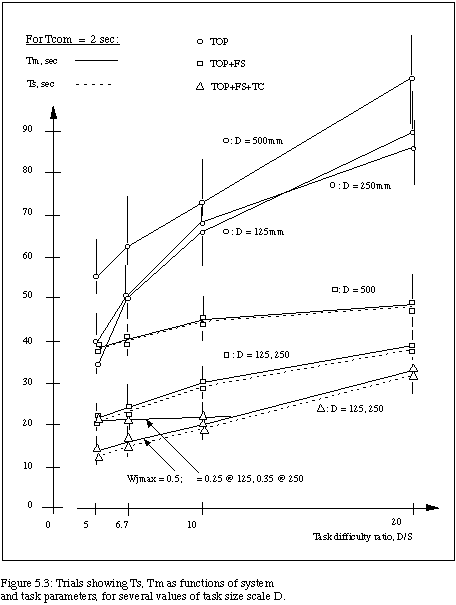
The results in Figures 5.2 and 5.3 are displayed for the three relevant modalities of control, 1) teleoperation (TOP), 2) teleoperation with forward simulation (TOP+FS), and 3) teleoperation with forward simulation enhanced by time clutching (TOP+FS+TC). Figures 5.2 and 5.3 show the median values of task times as a function of the system parameters for the different modes of operation. The vertical lines which bracket each median value indicate the full range of specification/manipulation time results for the set of (six to ten) trials at that point in the parameter space.
We note that a comparison of TOP and (TOP+FS) in Figure 5.2 repeats experiments of Sheridan, et al, [NOY84], [SHE86], confirming the results of that work. We see that (TOP+FS) gives a significant gain in both Tspec and Tm over TOP alone. Then we notice that (TOP+FS+TC) gives another significant gain in Tspec over (TOP+FS). In the initial trials, we found that Wjmax = 1.0 rad./sec. was high enough for the robot's Tm time to keep up with even the shortest (TOP+FS+TC) Tspec times (see Fig. 5.3). We then found that Wjmax = 0.5 rad./sec. constrained Tm so that subjects could easily outpace the robot and save up time (see Fig. 5.2). This velocity limit is much greater than the velocity limits of the RMS; hence, for space applications the operator could very often outpace the robot. Many of the initially hypothesized forms of results were demonstrated using these parameter ranges.
Tspec and Tm grew less rapidly with respect to D/S than anticipated in the trials leading to results in Figure 5.2. We hypothesized that D = 500mm was large enough, given the joystick constants and Wj values, to produce dynamic constraints related more to the distance D than to the "difficulty" D/S. So, we repeated scaled versions of the trials at smaller values of D, producing the results of Figure 5.3.
These results of Figure 5.3 are interesting, because for all three modes the data per mode at D = 250mm and D = 125 mm essentially fall on top of one another. The 250mm and 125mm curves for each mode lie well below those for D = 500mm. Refer to Fig. 5.2 for the time-clutch mode data for D = 500mm (it would partly overly the Fig. 5.3 time-clutch data).
At this scale of D, the system operates in a "Fitts' law-like" region, with Tspec and Tm being functions of D/S (but not D), with the values in most cases at D/S = 20 about twice those at D/S = 5 (i.e., roughly a logarithmic function of D/S). For Wjmax = 0.5, the robot's Tm at this scale could stay up with operators' Tspec. We varied Wjmax and found values of 0.35 (for D = 250) and 0.25 (for D = 125) that yielded significant time differences between Tm and Tspec for (TOP+FS+TC) mode on the easier tasks (see Fig. 5.3).
On further scaling-down of D, the system enters its "noisy" region on the harder tasks (S < about 3mm). Position sample-sizes, interpolator discretization and operator jitters cause large increases and variances in Tm and Tspec (like trying to poke at things with a needle under a microscope).
Throughout the trials, subjects noticed striking differences in the "feel" of the different control modes, and developed special tactics for coping with each mode. Most treated TOP in the presence of delays like hitting a series of "successively shorter golf shots", trying to get closer each time. Subjects controlled (TOP+FS) aggressively, firmly driving the simulator to each switch. The (TOP+FS+TC) mode was usually handled with finesse, so as to drive it fast, but not so fast as to yield a wild path and thus large Tm and large Lm/5D.
The task times in general have positively skewed distributions, with medians smaller than means. Task times tends to cluster down towards subject and system performance limits at a given value of system parameters, occasionally straying to higher values when subjects make large errors requiring long correction times. The results indicate clear performance improvements of (TOP+FS) over TOP, and of (TOP+FS+TC) over (TOP+FS), for the indicated range of parameters, with separations of mean values for the different modes being at least several times the standard deviations.
In addition to these early quantitative results, we have demonstrated use of the position clutch to enable graceful hand-offs of control by one agent to a rendezvous of control by another agent. This is done by having two human operators swap use of the controls following disengagement of the position clutch when the forward simulation is out well ahead of the telerobot. We have compiled a video report showing the above experiments and control effects [CON87].
Teleautonomous technology presents many challenges in human-computer interaction. We have proposed a set of interface controls that are conceptually simple and easy to mechanize. The controls are generic and may be applicable in many different specialized situations. They are also cognitively and manipulatively accessible to the uninitiated by analogy, but many other new human interface aspects haven't been pinned down at all. How is the operator to visualize where they are, who has control of what, and who they give control to next as they enter or leave some subtask within a complex task lattice? What measures can we provide concerning operator performance, and what feedback can we provide? And what about the analysis and design of cognitive and manipulation tasks themselves? Research can perhaps provide better measures of joint human-machine cognitive-manipulative performance. Analyses similar to those in [CAR83] may then lead us to design intermixings of human and machine activity that yield substantial improvements in overall performance.
The work poses some additional challenges in robotics, such as the eventual need to perceive, model and forward simulate not only the remote teleautomaton, but also portions of the remote environment itself. Forward simulation will work fine when interacting with static objects, but what about interactions with moving objects? The simulation based methods we have discussed are dependent, in pure form, entirely upon the quality of the robot and environment models available and the accuracy with which tasks must be performed. In all of our experimental tests to date, the accuracy required was well below the accuracy of the models, and this was not a problem. However, most assembly tasks involve contact among the parts and have much higher accuracy requirements. Moreover, independent of accuracy requirements, even small errors when contacts are involved can produce very high, possibly damaging, forces. Solutions for this important class of problems is essential for many, if not most, applications. [VOL88] describes these basic problems in greater detail and outlines a number of possible directions for solution.
Further work is needed on methods for path-error specification and associated methods for the time optimization of path following, such as in [SUH87]. Additional work is also needed on autonomous "reflex" actions that the remote robot can perform when encountering uncertainties (particularly those involving contact) not modeled in the forward simulation.
Certain dimensions of teleautonomy may have near-term utility. For example, most of the basic technologies exist for developing "remote coaching" systems in which a local expert can coach a remote technician in complex tasks. One prototype remote coaching system is described in [WAL88]. The prototype includes a modest, but extensible, expert system in the remote controller that can help the technician with most problems and call in the expert when needed. The system allows graphic or image data objects to be selected from a library and placed on workstation screens for both the technician and the expert. The expert has a graphic capability for drawing on both screens, as well as being in voice contact with the technician, and slow scan video support is available. However, research is still needed to explore means to better support on-line interactions in the face of communications delays.
We have pointed out that there is a growing need in many areas of our society to be able to achieve remote intelligent action at a distance, and that traditional methods of automation and artificial intelligence are inadequate for such tasks. We have further introduced three dimensions that characterize the problem space: 1) the type of process being performed (perception, cognition, and/or action), 2) the form that is performing the process (human, robot, automatic vehicle, etc.), and 3) the location at which the process is being performed. We have coined the term teleautonomous systems to describe systems addressing this problem space. Teleautonomous systems are represented by a set of points in this space spread across more than one location plane.
One of the most fundamental problems that must be overcome in building such teleautonomous systems is time delay resulting from telemetry or signal propagation. Simulation of remote devices and environments is part of the solution. We have introduced the notions of time and position de-synchronization (implemented through time and position clutches) to allow the simulation to be operated faster than real time and to permit an on-line "motion editing" to be achieved. Our early experiments involving the use of such time and position clutches suggest that significant improvements in performance can be achieved through the use of these clutches, even when there is no time delay. Moreover, the time and position clutches can be used to accomplish a new interaction protocol for hand-offs between two agents controlling a remote device. This protocol is based upon a shared visualization of the intended motion of the device.
We believe that teleautonomous systems research can yield methods and systems for improved projection of intelligent action at a distance in time and space. This interdiscipline presents interesting new research opportunities to teams having expertise in robotics and automation, artificial intelligence, and the psychology of human-computer interaction.
We gratefully acknowledge support from the Research Excellence Fund of the State of Michigan, support provided by the grant of a high performance IRIS graphics workstation from Silicon Graphics, Inc., and the contributions of Lee Hagerhorst and Lejun Shao to the rapid prototyping of our first experimental systems.
[AND89] J. Andary, D. Hewitt, and S. Hinkal, "The Flight Telerobotic Servicer Tinman Concept: System Drivers and Task Analysis", NASA Conference on Space Telerobotics, NASA, Jan. 31-Feb.2, 1989.
[BEK61] G. A. Bekey and J. Lyman, "Sampled Data Models of the Human Operator in a Control System: A Progress Report", 1961 Symposium on Biomedical Engineering, 20-21 April 1961, San Diego, CA.
[BER66] R. Bernotat and H. Widlok, "Principles and Applications of Prediction Display", Institute of Navigation, 19(3):361-370, July 1966.
[CAR83] S. K. Card, T. P. Moran and A. Newell, The Psychology of Human-Computer Interaction, Lawrence Elbaum Assoc., Hillsdale, NJ, 1983.
[CON87a] L. Conway, R. Volz and M. Walker, "New Concepts in teleautonomous Systems," Second AIAA/NASA/USAF Symposium on Automation, Robotics and Advanced Computing for the National Space Program, March 11, 1987.
[CON87b] L. Conway, R. Volz and M. Walker, "Teleautonomous Systems: Methods and Architectures for Intermingling Autonomous and Telerobotics Technology", Proceedings of the IEEE International Conference on Robotics and Automation, March 30,1987.
[CON87c] L. Conway, R. Volz and M. Walker, "New Concepts in Teleautonomous Systems," University of Michigan Robotics Research Laboratory Video-Report, February 1987.
[CON88] L. Conway, R. Volz and M. Walker, "Teleautonomous System and Method Employing Time/Position Synchrony/Desynchrony, U.S. Patent Application, March 10, 1988. [Note: this later issued as U.S. Patent 5,046,022, on Sep. 3, 1991.]
[DRA87] J. V. Draper, J. N. Herndon and W. E. Moore, "The implications of force reflection for teleoperation in space", 1987 Goddard Conference on Space Applications of Artificial Intelligence and Robotics, May 1987.
[ESS85] Essex Corporation, "The Solar Max Repair Mission", Final Report to NASA, Contract NAS5-27345, Essex Report No. N-85-05, June 25, 1985.
[FER67] W. R. Ferrell and T. B. Sheridan, "Supervisory Control of Remote Manipulation", IEEE Spectrum, pp. 81-88, October 1967.
[GOE52] R. C. Goertz, "Fundamentals of general purpose remote manipulators", Nucleonics, 10:36-42, Nov. 1952.
[GRE88] I. Greif, Ed., Computer-Supported Cooperative Work: A Book of Readings, Lotus Development Corp., Morgan Kaufmann, New York, May 1988.
[HAR89] F. Harrison, "System Architectures for Telerobotic Research", NASA Conference on Space Telerobotics, NASA, Jan. 31-Feb.2, 1989.
[HIL79] J. W. Hill, Study of modeling and evaluation of remote manipulation tasks with force feedback, NASA Technical Report CR-158721, July 1979.
[JAU89] B. Jau, "The Jau-JPL Anthropomorphic Telerobot", NASA Conference on Space Telerobotics, NASA, Jan. 31-Feb.2, 1989.
[KAN89a] E. Kan, J. Tower, G. Huncka and G. VanSant, "The JPL Telerobot Operator Control Station: Part I - Hardware", NASA Conference on Space Telerobotics, NASA, Jan. 31-Feb.2, 1989.
[KAN89b] E. Kan, P. Landell, S.Oxenberg and C. Morimoto, "The JPL Telerobot Operator Control Station: Part II - Software", NASA Conference on Space Telerobotics, NASA, Jan. 31-Feb.2, 1989.
[KEL67] C. R. Kelley, "Better Control for Complete Manual Systems", Control Engineering, pp.86-90, August 1967.
[KUG72] D. A. Kugarth, Experiments evaluating compliance and force feedback effect on manipulator performance, NASA Technical Report CR-128605, August 1972.
[MAT89] J. Matijevic, W. Zimmerman and S. Dolinsky, "The Architecture of the NASA/OAST Telerobot Testbed", NASA Conference on Space Telerobotics, NASA, Jan. 31-Feb.2, 1989.
[MCC65] W. K McCoy and G. G. Frost, "Predictor Display Techniques for On-Board Trajectory Optimization of Rendezvous Maneuvers". Final Report AMRL-TR-66-60, Ritchie Inc., Dayton, Ohio, April 1965.
[MIL85] P. Milgram and P. H. Wewerinke, "Model Analysis of Remotely Controlled Rendezvous and Docking with Display Prediction", Annual Conference on Manual Control (21st), National Aerospace Laboratory, Amsterdam, June 1985.
[MOL87] J. Molino, "Robotics development facility preliminary engineering results", Flight telerobotic servicer in-house phase-B study, First NASA/Industry Briefing, December 1987.
[MUR66] G. J. Murphy, Basic Automation Control Theory, D. Van Nostrand Company, Inc., Princeton, NJ, 1966
[NAS81] NASA, "Shuttle Flight Operations Manual, Payload Deployment and Retrieval Systems," Vol. 16; Flight Operations Directorate, Johnson Space Center, June 1, 1981.
[NAS86] Pioneering the Space Frontier, U.S. National Commission on Space, NASA, Library of Congress, 1-211, May 1986.
[NAS88] Advancing Automation and Robotics Technology for the Space Station and for the U.S. Economy: Progress Report 6 - October 1987 Through March 1988, NASA Technical Memorandum 100989, June 15, 1988.
[NOY84] M. Noyes and T. B. Sheridan, "A Novel Predictor for Telemanipulation through a Time Delay", Proc. of the Annual Conference on Manual Control, NASA Ames Research Center, Moffett Field, CA, 1984.
[PHA69a] A. V. Phatak and G. A. Bekey, "Model of the Adaptive Behavior of the Human Operator in Response to a Sudden Change in the Control Situation", IEEE Transactions on Man-Machine Systems, Vol. MMS-10, No. 3, Sept. 1969, pp 72-80.
[PHA69b] A. V. Phatak and G. A. Bekey, "Decision Processes in the Adaptive Behavior of Human Controllers", IEEE Transactions on Systems Science and Cybernetics, Vol SSC-5, No. 4, Oct. 1969, pp 339-351.
[RID87] S. K. Ride, Leadership and America's Future in Space, NASA, August 1987.
[RTI82] RTI, RTI Force Sensing Wrist User's Manual, Robot Technology, Inc., Los Altos, CA, 1982.
[SHE86] T. B. Sheridan, "Human Supervisory Control of Robot Systems", Proc. of the IEEE International Robotics Conference, April 1986, pp. 808-812.
[SUH87] S. H. Suh and A. B. Bishop, "Tube Concept and Its Application to the Obstacle Avoidance Minimum-Time Trajectory Planning Problem," Univ. of Michigan Robotics Laboratory paper submitted to the IEEE Journal of Robotics and Automation.
[VER86] J. Vertut and P. Coiffet, "Teleoperations and Robotics: Applications and Technology," Robot Technology, Vol. 3B, English Trans., Prentice-Hall, 1986.
[VOL88] R. Volz, L. Shao, M. Walker and L. Conway, "Teleautonomous Control Involving Contacts," Technical Report, RSD-8-88, University of Michigan, Robotics Research Laboratory, 1988.
[WAL88] M. Walker, S.-Y. Sheu, R. Volz and L. Conway, "A Low Cost Portable Teleautonomous Maintenance Station," presented at the USAF/NASA Space Operations Automation and Robotics Workshop ("SOAR '88"), Dayton, OH, July 1988.
[WIL89] B. Wilcox, K. Tso, T. Litwin, S. Hayati and B. Hon, "Autonomous Sensor Based Dual-Arm Satellite Grappling", NASA Conference on Space Telerobotics, NASA, Jan. 31-Feb.2, 1989.
Biographical sketches:
Lynn Conway (SM'79-F'85) received the B.S. and M.S.E.E. degrees at the School of Engineering and Applied Science, Columbia University, New York, NY in 1962 and 1963, respectively.
After having worked for IBM Corporation, Yorktown Heights, NY, and Xerox Palo Alto Research Center, Palo Alto, CA, she joined the Defense Advanced Research Projects Agency as Chief Scientist and Assistant Director for Strategic Computing in 1983. During 1978-1979 she also served as Visiting Associate Professor of Electrical Engineering and Computer Science at Massachusetts Institute of Technology, where she taught the initial prototype of the VLSI design course that has since revolutionized microelectronics design practice worldwide. Since 1985, she has been Professor of Electrical Engineering and Computer Science and Associate Dean of the College of Engineering at the University of Michigan, Ann Arbor, MI. In her research, she is active in the areas of collaboration technology and robotics. She is co-author of Introduction to VLSI Systems, and the recipient of the Harold Pender Award of the Moore School of Electrical Engineering, University of Pennsylvania, the Secretary of Defense Meritorious Civilian Service Award, and the John Price Wetherill Medal of the Franklin Institute. In 1987 she was selected as a Member of the U. S. Air Force Scientific Advisory Board.
Ms. Conway is a Member of the National Academy of Engineering.
Richard A. Volz (SM' 86) received the Ph. D. degree from Northwestern University, Evanston, IL, in 1964.
He was Associate Chairman of the Electrical and Computer Engineering Department and Associate Director of the University Computing Center at the University of Michigan, as well as Director of its Robotics Research Laboratory. At present, he is Department Head and Professor of Computer Science at Texas A&M University, College Station, TX, and Director of the Computer Science Division of the Texas Engineering Experiment Station. He served on the Automation and Robotics Panel of experts NASA established to advise NASA on how to incorporate A & R technology into the Space Station. He is currently a member of the Aerospace Safety Advisory Panel for NASA and Congress, and has served as a member of the Ada Board, the Department of Defense's advisory board for policy on the programming language Ada. His current research interests include distributed computer systems, manufacturing software, embedded real-time computer systems, and robotics in particular task planning, programming and teleautomation.
Michael W. Walker (M '87) received the B.S. degree from Mississippi State University in 1973, and the M.S. and Ph.D. degrees from Purdue University, West Lafayette, IN, in 1975 and 1978, respectively, all in electrical engineering.
After graduating from Purdue University, he worked for five years in industry, two years at the Aerospace Corporation in El Segundo, CA, and three years at the Nordson Corporation in Amherst, Ohio. He then joined the Electrical Engineering Department at Clemson University, Clemson, SC as an Assistant Professor. Since 1985 he has been an Associate Professor in the Electrical Engineering and Computer Science Department at the University of Michigan, and is an active member of the Robotics Research Laboratory. His current research interests are in the fields of telerobotics, teleautonomous systems, and manipulator kinematics, dynamics and control.