ADVANCED COMPUTING SYSTEMS
SAN JOSE
February 23, 1966
MEMORANDUM TO: File
SUBJECT: DYNAMIC INSTRUCTION SCHEDULING (DRAFT)
L. Conway
B. Randell
D. P. Rozenberg
D. N. Senzig
-p.1-
INTRODUCTION
The order in which the instructions comprising a program are to be executed is normally assumed to be given by the order in which the instructions are held in program storage and by the sequencing control indicated by transfer and conditional transfer instructions. However a programmer, or compiler, can produce many different but equivalent versions of a program merely by making minor alterations to the sequence in which instructions are placed. Normally the actual choice among these alternative sequences will be somewhat arbitrary, though careful programming or compilation often involves an attempt to design a program whose detailed sequences are tailored to make best use of a computer's control and functional capabilities. This can be particularly worthwhile for computers whose internal organization has been designed to attempt to overlap the use of its various functional capabilities.
Take, for example, a computer which initiates execution of instructions in strict sequence, without necessarily awaiting the completion of one instruction before execution of the next instruc-tion, provided that the operands of the second instruction are ready, and the necessary busses and functional units are available. In such a computer the sequence (written here for convenience in a 3-address format)
R1 + R2 -> R3
R1 x R4 -> R5
R6 + R2 -> R7
R3 x R6 -> R8
might well be preferable to
R1 + R2 -> R3
R6 + R2 -> R7
R1 x R4 -> R5
R3 x R6 -> R8
if the adder and multiplier were independent functional units.
-p.2-
Thus if really effective use is to be made of the internal capabilities of such a computer, careful attention must be paid to the detailed sequencing of instructions in frequently' executed portions of a program. This 'scheduling' can be done by an ambitious optimizing compiler, or an extremely conscientious hand-coder. There is often, however, a difficulty in achieving really optimum sequencing by such means -- that of the effects of memory interference, which if present will cause variations in the times which operands take to reach the arithmetic and control unit from storage.
The effects of such memory interference will not usually be calculable in advance of program execution, particularly if the inter-ference is caused by autonomous 1/0 units using the memory. Thus there is often cause to consider the possibility of supple-menting (or even replacing) the static scheduling performed by coder or compiler by dynamic scheduling performed by the computer as it executes a program. In this paper we describe a technique of dynamic scheduling permitting non-sequential instruction execu-tion. Furthermore, the technique presented is shown to be capable of controlling the simultaneous execution of two or more instructions at a time on machines with sufficiently generous bussing and func-tional capabilities. In any actual computer design care would of course have to be taken to ensure that any possible gains achieved by such dynamic scheduling were not offset by the cost (both in speed and in circuits) of the extra hardware necessary to perform the scheduling.
The scheme presented uses a very general, but conceptually
simple, method of controlling non-sequential instruction execution,
and of identifying groups of instructions which are mutually independent
and can be executed simultaneously. Brief descriptions of earlier
schemes for achieving some of these aims have been given by Amdahl
[1], Chen [2], and Thornton [3].
-p.3-
NON-SEQUENTIAL INSTRUCTION EXECUTION
In this section we restrict our attention to the sequencing of straight line coding comprised of instructions, the locations of whose operands and results can be determined directly from the instructions themselves, rather than needing any address computation to be performed.
The sequence in which a series of instructions have been written implies the total effect that these instructions are intended to have when executed. Each separate instruction-contributes to this total effect by performing its operations on the contents of certain registers (accumulators, index registers, indicators, etc.) and setting its results into other registers. A dynamic scheduling technique has to insure that any instructions obeyed out of sequence do not change the contents of any registers which are to be used by any instructions whose execution has been delayed temporarily.
A simple set of rules for determining if a given-instruction can be obeyed out of sequence is as follows:
(i) The required busses and functional units are available.
(ii) The instruction must not use any registers which are used as result registers by instructions whose execution has been initiated but not yet completed.
(iii) The instruction must not use as result registers any registers which are used as operand registers by any preceding instructions which have not yet been initiated.
(iv) The instruction must not use any registers (either as result or operand registers) which are used as result registers by any preceding instructions which have not yet been initiated.
These checks can be made in a systematic fashion using what are here called 'sequencing matrices'. Two matrices are used, namely a 'source matrix' (S) and a 'destination matrix' (D). At each cycle, when the machine is attempting to choose an instruction to be executed, rows in these matrices are set up corresponding to each of the instructions which are being considered by the scheduling mechanism. (The cycle referred to above is a clock cycle, which corresponds to the maximum rate at which instructions can be initiated, and will presumably be much shorter than a storage cycle.) The elements in each row of the matrices indicate whether a given register is being used, or will be affected, by the corresponding instruction.
-p.4-
The element Si,j is set to one if the ith instruction uses
the contents of register j as an operand. The element Di,j is
set to one if execution of the ith instruction will cause the
contents of register j to be replaced.
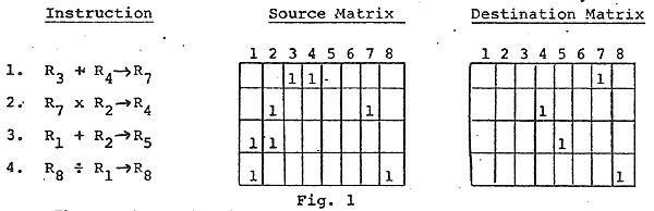
Take, for example, a very simple machine with eight registers and a 3-address format, using a scheduling mechanism that processes four instructions per-cycle. A typical situation would be:
Thus each row has been set up by processing the register address fields of the corresponding instructions, and converting these addresses into unary form. However in more realistic machines the setting up of the matrix elements would not be so straightforward. Almost certainly it would involve decoding the operation code part of the instruction to determine what implied registers are used by an instruction in addition to those indicated by address fields.
In addition to the matrices, which provide a conveniently coded form of indicating the register requirements of instructions awaiting execution, a 'busy vector' (B) is used to indicate the current status of the machine registers. The length of the vector is equal to the number of registers. The element Bj is set to one when execution of an instruction which will cause the contents of register j to be replaced is initiated; it is reset to zero when the replacement has been completed.
Once the sequencing matrices and the busy vector have been set up as described, the basic algorithm for choosing an instruction to be executed can be described as follows. Starting with the top row of the matrices, each instruction is checked--instruction i can be executed if:
(i) The required busses and functional units are available.
(ii) The elements of B corresponding to the non-zero elements of the ith rows of S and D are zero.
-p.5-
(iii) The elements above row i of the columns of D corresponding to the non-zero elements of row i of S contain only zeroes.
(IV) The elements above row i of the columns of S and D corresponding to non-zero elements of row i of D contain only zeroes.
Returning to the previous example, with the busy vector set up to indicate that certain registers, 3 and 6 for instance, are still to have their contents replaced, by the action of previously initiated instructions

Instruction 1 cannot be executed because of rule (ii)
Instruction 2 cannot be executed because of rules (iii) and (iv)
However instruction 3 can be executed, provided that the necessary bussing and functional capabilities are available.
Each cycle; while the scheduling mechanism is attempting to choose an instruction to initiate, a decoding mechanism could be processing a further instruction, taken from the address in the instruction store given by an instruction counter. In contrast to a conventional instruction counter, this counter does not indicate which instruction is currently being executed, but rather which instruction is next in line for processing by the scheduling mechanism. With non-sequential instruction sequencing it is not possible to have a conventional instruction counter. This can in certain circumstances be a disadvantage of the system, and is discussed further below.
At the end of a cycle, if an instruction has been chosen (it is of course possible that none of the instructions can be initiated until some of-the non-zero elements of the busy vector become zero), the rows corresponding to the instruction are removed from the matrices. The remaining rows are then pushed upwards
-p.6-
to fill in any gap, the bottom row of the matrix is replenished using the instruction which has just been decoded, and the instruction counter is incremented. All is then ready for the scheduling mechanism to again scan the matrices in an attempt to choose another instruction to initiate.
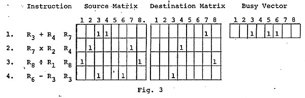
In the above example, the situation at the start of the next cycle might be (assuming that registers 3 and 6 have still not had their contents replaced) as shown in Fig. 3. During this cycle the Divide instruction will be chosen for execution.
In the above general description of the proposed technique for non-sequential instruction execution the discussion has been limited to the scheduling of straight-line coding composed of instructions whose register requirements can be determined immediately from inspection of the instructions. The next two sections of this paper deal with the effect of unconditional and conditional branch instructions, and with a technique for scheduling instructions which refer to indexed addresses in storage.
-p.7-
UNCONDITIONAL AND CONDITIONAL BRANCHING
There is one kind of branch instruction, namely the unconditional branch to an explicit instruction address, which can be handled very simply, without recourse to the sequencing matrices. The instruction is executed as soon as it has been decoded, causing the appropriate modification to the instruction counter which indicates the location from which the sequencing matrices are to replenished.
The other types of branch instructions, where the branch address and/or the question of whether the branch is to be taken cannot be determined directly from the instruction, but rather depend on the contents of one or more registers, cause rows to be entered into the sequencing matrices in the usual way. However refilling of the matrices then stops until the branch instruction has been executed and any necessary modification has been made to the instruction counter. Thus once such a branch instruction has entered into the matrices, the matrices will gradually empty until the execution of the branch instruction permits refilling to begin. This means that every effort should be made to initiate execution of the branch instruction as soon as possible, and that once the branch instruction has been executed, empty rows of the matrix should be replenished as quickly as possible. Otherwise, the matrices will spend much of their time only partly full, and the chances of finding an executable instruction each cycle will be considerably reduced.
Since a scan of the matrices enables all the executable instructions to be identified, what is required is to ensure that a branch instruction is given priority over any other executable instructions. The simplest way of doing this, since there can never be any instructions in the matrices below a branch instruction, is to always choose the lowest executable instruction, whether or not this is a branch instruction. However it could be argued that this is taking unnecessary liberties with the sequencing of a program, which will cause undue complications in program debugging. The alternative is to arrange some system whereby if there is an executable branch instruction it is initiated, but that otherwise the highest executable instruction is chosen.
The second requirement, that of speedy replenishment of the matrices once a branch instruction has been executed, required decoding facilities operating in parallel on several instructions. The alternative of relying solely on the normal decoding and replenishment mechanism, which fills only one row each cycle, is unlikely to be adequate.
An 'Execute' instruction, which can be regarded as a temporary branch for the duration of a single instruction, involves only slight extensions to the above system. Filling of the matrices is halted once an Execute instruction has been reached, until it can be obeyed and the instruction which it specifies can be fetched
-p.8-
and placed in the matrices. Unless this is another Execute instruction, or a branch instruction, filling of the matrices can then be resumed, starting with the instruction following the original Execute instruction.
-p.9-
THE SEQUENCING OF STORAGE ACCESSES
Another area where dynamic scheduling can be of value is the sequencing of accesses interleaved storage. Such storage is char-acterised by the fact that access to one of the autonomous memory units, or of which the storage is comprised does not have to await the completion of previous accesses to other boxes. Rather, storage accesses can be made at the rate at which they can be accepted by the bussing system, provided that repeated accesses to the same box are sufficiently separated. Thus the problem of sequencing storage accesses can be regarded as having similarities to that of sequencing instructions, with boxes taking the place of registers, and 'bus slots' the place of clock cycles.
The particular box involved in a storage access is determined
from the effective address of the location to which access is
being made (typically a group of the least significant digits
of the address
is used). Such an address will normally be the result of a calculation
involving the contents of one or more registers. Thus the box
used by a storage access requested by a register load or store
instruction cannot be determining directly by examination of the
instruction, it being necessary to wait until the effective address
can be calculated.
Though one can conceive of a single scheduler being used for sequencing both instructions and storage accesses, it seems more reasonable to have a second scheduler just for sequencing storage accesses, operating in conjunction with the instruction scheduler. The storage access scheduler could operate according to the same general principles as the instruction scheduler, using source and destination matrices (SA and DA, say), and a busy vector (BA), whose respective columns and elements correspond to the various boxes. It would receive requests for storage accesses both from the instruction scheduler, on behalf of load and store instructions, and from the instruction fetch mechanism which is used to replenish the instruction scheduler.
The instruction scheduler described above is designed on the assumption that once an instruction is removed from the matrices and issued, it no longer has any demands on the registers that it uses for its operands. Therefore, a set of buffer registers are included in the storage access scheduling mechanism to hold the contents of registers which are to be stored, until the required storage access can be initiated.
Certain constraints must be placed on the order in which storage access requests can be issued to the storage access scheduler from the instruction scheduler. For example, a store request must not be issued to the storage access scheduler before any preceding load request. Only when the boxes involved in these requests have been determined will it be possible for the storage access scheduler to
-p.10-
perhaps make such modifications to the sequencing of storage access requests. In fact what is necessary is for the instruction scheduler to treat the store as a single extra register. Therefore an additional column is added to the S and D matrices, and an element is added to the busy vector. However this extra busy vector element is not set to one unless the storage access scheduler is unable to accept any further storage access requests. All load instructions have the extra element in their row of the S matrix set to one; all store instructions have the extra element in their row of the D matrix set to one. The normal sequencing rules will then apply the necessary constraints to the issuing of access requests.
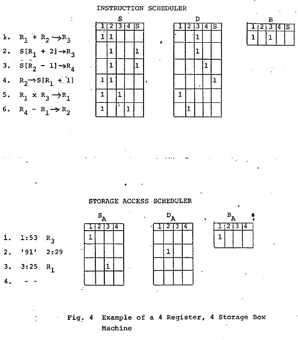
Figure 4 demonstrates the setting of the matrices and busy vectors of the two schedulers on a machine with 4 registers and 4 storage boxes. The instruction scheduler processes six instructions per cycle; the storage access scheduler processes four-access requests per bus slot. Instructions are either 3-address format, or specify single-indexed loads and stores. The vector B indicates that registers R1 and R3 are still involved with previously initiated instructions, and that the storage access scheduler has capacity for further storage access requests. The storage access scheduler contains only three access requests -- a load of register R3 from address 53 in box 1, and a store of the literal 91 (the contents of some register) in address 29 of box 2, and a load of register R from address 25 of box 3. The vector BA indicates that box 1 is still involved in some earlier access request.
When the instruction scheduler initiates execution of a load or store instruction the rows corresponding to the instruction are removed from the S and D matrices, and the B vector (except for the last element, corresponding to the store) is updated in the usual way. The effective address is calculated, and it and the address of the register to be loaded or stored are transmitted to the storage access scheduler (together with the contents of the register, in the case of a store instruction). This storage access request causes the highest unoccupied row of the matrices SA and DA to be set up so as to indicate the box requirements of the request.
-p.11-
-p.12-
The matrices SA and DA are scanned each bus slot time, in order
to choose an access request which can be issued ahead of any preceding
requests which are held up, and which does not involve a box indicated
by the vector B as being still involved with a previous access.
The corresponding to this request are removed from the matrices,
the rows are pushed up to fill in the gap, and the busy vector
updated. When a storage access to a box has been completed the
corresponding element
of BA is made zero once again. If this access was on behalf of
a load instruction, the appropriate element of B is made zero
when loading of the register has been completed.
Returning to the example demonstrated in Fig. 4, the situation after one machine cycle and bus slot time is shown in Fig. 5. The third instruction, a load instruction, has been chosen for execution, the effective address specified by it has been calculated to be location 57 of box 4, and it has been issued as an access request to the storage access scheduler. Meanwhile the second storage access request has been issued, the preceding request being still blocked because the required box is still involved in an earlier access.
-p.13-

-p.14-
There are many possible variations on this scheme for sequencing storage accesses. For instance, one can dispense with extra buffer registers and continue to hold quantities in the working registers until the appropriate memory unit can be accessed. What is required to avoid unessential slowing down of the instruction scheduler is that the registers used in the calculation of the effective address be released before the instruction is necessarily removed from the matrix. This introduces a new complexity. Previously an instruction was not modified in the matrices, except for its possible bubbling towards the top, until its complete removal from the matrices.
The bits in the source matrix corresponding to those components of the effective address calculation would beset to zero as soon as they are used. This at least releases those registers for use in further calculations. One might further refine interlocking on register usage so that effective address calculations were performed before the contents of the register to be loaded or stored were available.
Indirect addressing can be handled in much the same way as branch and execute instructions. If the various levels of indirect addressing use new indexing registers at each step then no instruction can be permitted to be executed which may result in any register modification. Unless memory read buffers are present this effectively means that indirect addressing will stop instruction initiation though matrix replenishment can proceed. If indirect addressing does not require new indexing registers but simply generates new memory store access requests then only succeeding store instructions must be inhibited until the indirect addressing chain is terminated.
-p.15-
SIMULTANEOUS EXECUTION OF INSTRUCTIONS
The instruction scheduling method described above uses the sequencing matrices in order to detect which instructions can be obeyed out of sequence. As a byproduct it automatically detects which instructions can be initiated simultaneously, at least in so far as register usage is concerned. Thus, given sufficient functional capabilities and sufficient busses between registers and functional units, the scheduling scheme can he used to control the simultaneous initiation of instruction execution. The matrix scanning algorithm would remain unchanged, though from a hardware point of view if not conceptually the procedure for compressing the remaining rows in the matrices upwards to fill in any gaps becomes more complex.
We assume that the machine has a number of independent functional units in addition to the memory and branch control units. Typical additional independent specialized functional units are floating point add/subtract, multiply, and divide units. We make the further assumptions that each functional unit has a buss connecting with the registers and that there is only one functional unit of each type. The complexities that arise when these assumptions are removed will be discussed below.
The requirements for simultaneous initiation of instruction execution is the addition of a bit to the busy vector for each functional unit that cannot accept operands every cycle and a column appended to the destination matrix for every functional unit.
The busy vector bit corresponding to the functional unit is turned on by the initiation of execution of an instruction in the corresponding functional unit. The busy vector bit is turned off when the functional unit is able to accept a new operand pair.
Rule (i) of the sequencing algorithm given informally above can here be stated as: the elements of B representing the functional units must have zeros corresponding to non-zero elements in the ith row of D. The elements above row i of the columns of D corresponding to the non-zero elements of D contain only zeros.
The operation code portion of the instruction is decoded to the extent that it is known which functional unit is going to execute the instruction. This information sets a one in the bit position whose row index corresponds to the instruction and whose column index corresponds to the functional unit.
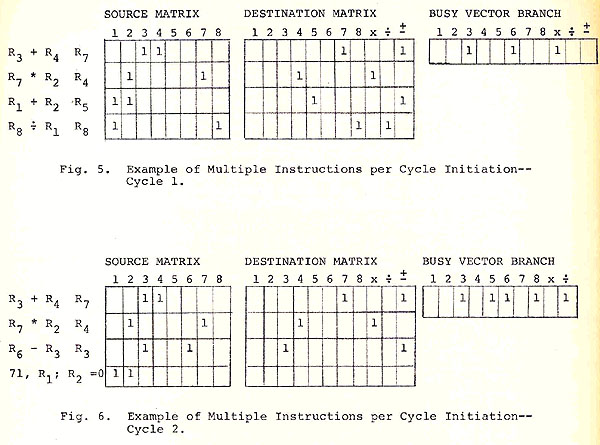
Going back to the example used in Fig. 2 and assumming that
the functional units are an add/subtractor that can accept a new
pair of operands every cycle, a multiplier and a divider that
cannot accept a new pair of operands every cycle, and a branch
controller, we have the situation shown in Fig. 5.
-p.16-
As in Fig. 2, Instruction 1 cannot be executed because of rule (ii). Instruction 2 cannot be executed because of rules (iii) and (iv). In addition Instruction 2 cannot be executed because of rule (i), i.e., because the multiplier is busy. The execution of Instructions 3 and 4 can be initiated -- they violate of the rules on register usage and the appropriate functional units are free.
As is done in the sequential case, at the end of the cycle, instructions that have been chosen for execution are removed from the matrix. The remaining rows are pushed up to fill in the gaps, and new instructions are inserted at the bottom of the matrix to replace those which have been initiated, and the instruction counter is incremented.
In the above example (Fig. 5) the situation during the next cycle might be as shown in Fig. 6. The instructions 1 and 2 are inhibited by the same reasons as before. Since the Busy vector bit corresponding to the Branch unit is zero (indicating no Branch instructions in the matrix) new instructions can be entered. The new instruction 3 (R6 - R3 ->R3 ) is inhibited by rules (ii) and (iv).
The new fourth instruction specifies a branch to the memory locations specified by the contents of register R1 plus 71 if register R2 contains a zero. Since all of the registers used by this instruction are free this instruction can be initiated. Since we still can have but one branch instruction in the matrix at a time no Branch column on the Destination matrix is needed though the equivalent may be needed by the replenishing mechanism. The Branch bit on the Busy Vector is needed to inhibit the matrix replenishing hardware.
In the case of the sequential control the point was made that preference should be given to branch instructions. Here, because one can say that each functional unit is looking for work, no special priority need be given to a branch instruction.
-p.17-
-p.18-
If more than one functional unit of a given type exists but each has its own busses then it is necessary to add a bit to the busy vector corresponding to the new functional unit. No additional columns are added to the Destination Matrix.
In the discussions above it has been tacitly assumed that the functional units were completely passive since the scheduler dispenses operands to the functional units for execution. If instead one takes the approach that the functional units are active, and that the sequencing matrixes are used by the functional units to provide the necessary interlock information then the handling of multiple functional units of a given type is perhaps easier to envision. The functional unit then executes the uppermost instruction that has a one in the column of the Destination Matrix corresponding to the functional unit and has its registers free. With multiple functional units the individual functional units must in addition check the status of all life functional units.
If the number of instructions that can be initiated per cycle is restricted by the number of busses, i.e., one has fewer busses than functional units or rows in the sequencing matrices, one can then take the approach that each instruction uses a functional unit called buss in addition to the functional unit explicitly requested by the instruction.
-p.19-
CONCLUSION
In this paper we have described a dynamic scheduling mechanism for providing a look-ahead capability which enables the execution of instructions to be initiated out-of-sequence. In addition the mechanism is capable of controlling the simultaneous initiation of two or more instructions.
The generality of register and functional unit interlocking provided by the mechanism may well be in excess of what is necessary for a given computer design. The modifications to suit any particular design will usually be reasonably obvious and are beyond the scope of this paper.
-p.20-
REFERENCES
1. G.M. Amdahl. Engineering Aspects of Large, High-Speed Computer Design; Part II--Logical Organization. Paper presented at the Office of Naval Research Symposium on High-Computer Hardware, November 17-18, 1964, Washington D. C.
2. T. C. Chen. The Overlap Design of the IBM System/360 Model 92 Central Processing Unit. AFIPS Conference Proceedings Vol. 25, Part 2. 1964 Spring Joint Computer Conference. Spartan Books, Washington D. C. (1964) pp. 73-80.
3. J. E. Thornton. Parallel Operation in the Control Data 6600. AFIPS Conference Proceedings Vol. 25, Part 2 Spring Joint Computer Conference. Spartan Books, Washington D. C. (1964) pp. 33-40.
lynnconway.com > ACS Archive front-matter > DIS Paper